| Product |
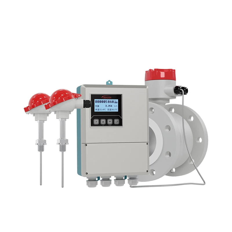
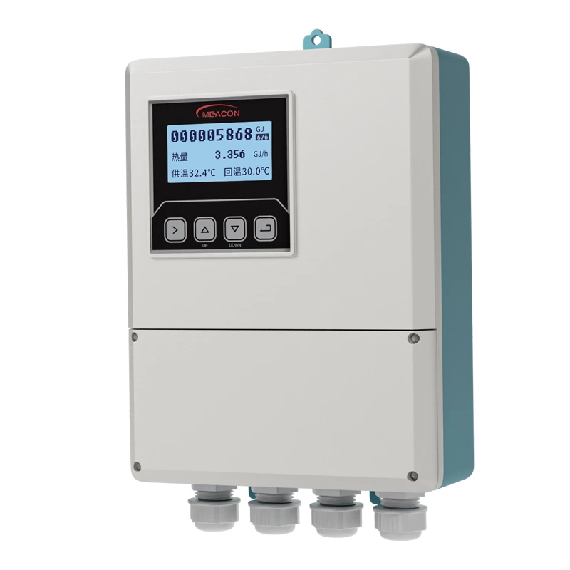
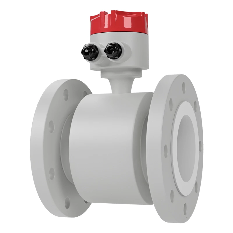
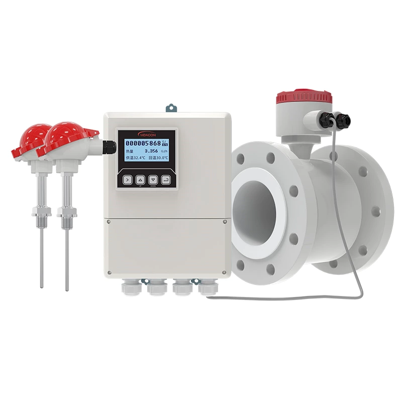
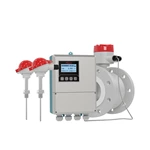
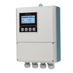
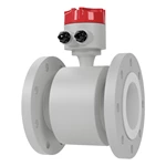
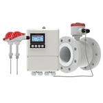
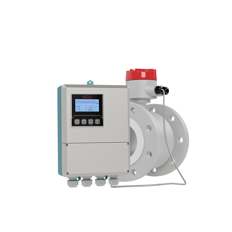
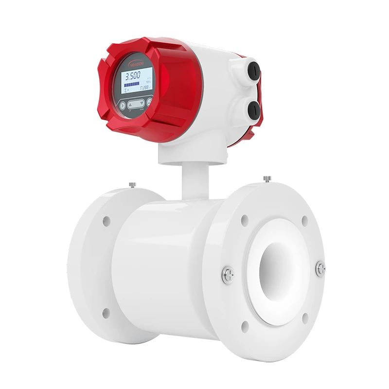
Electromagnetic BTU meter |
| Model |
MIK-LDGR |
| Diameter nominal |
DN15 ~DN1000 |
| Accuracy |
±2%, (flow rate=1m/s) |
| Working pressure |
1.6 MPa |
| Liner material |
PFA, F46, Neoprene, PTFE, FEP |
| Electrode material |
Stainless steel SUS316L, Hastelloy C, Titanium, |
| Tantalum, Platinum-iridium |
| Medium temperature |
Integral type: -10℃~80℃ |
| Split type: -25℃~180℃ |
| Power supply |
100-240VAC,50/60Hz, 22VDC—26VDC |
| Electrical conductivity |
> 50μS/cm |
| Ingress protection |
IP65, IP68 |
An electromagnetic BTU (British Thermal Unit) meter is a device used to measure the heat energy transferred in a heating or cooling system. It operates based on the principles of electromagnetic flow measurement combined with temperature sensors.
The meter consists of a flow sensor and temperature sensors. The flow sensor uses electromagnetic induction to measure the volumetric flow rate of the fluid, such as water or glycol, passing through the system. This information is crucial for determining the amount of heat energy being transferred.
The temperature sensors are typically installed at the inlet and outlet of the system to measure the temperature difference. By combining the flow rate and temperature difference data, the BTU meter can accurately calculate the amount of heat energy exchanged.
The electromagnetic BTU meter is commonly used in various applications, including district heating and cooling systems, HVAC (Heating, Ventilation, and Air Conditioning) systems, and industrial processes. It provides an accurate and reliable measurement of energy consumption, allowing for efficient energy management and billing.
In summary, an electromagnetic BTU meter is a device that utilizes electromagnetic flow measurement and temperature sensors to measure the heat energy exchanged in a heating or cooling system. It plays a vital role in monitoring and managing energy usage in various applications.
MIK-LDGR electromagnetic BTU meter(Heat meter) operating principle: Hot (cold) water supplied by a heat source flows into a heat exchange system at a high (low) temperature(a radiator, heat exchanger, or complex system consisting of them),Outflow at low (high) temperature, in which heat is released or absorbed to the user through heat exchange (note: this process includes energy exchange between heating system and cooling system).When water flow through the heat exchange system, according to the flow sensor of flow and matching the temperature of the sensor is given for the return water temperature, and flow through time, through the calculation of the calculator and display the system heat release or absorption.
Q = ∫(τ0→τ1) qm × Δh ×dτ =∫(τ0→τ1) ρ×qv×∆h ×dτ
Q: Heat released or absorbed by the system, JorkWh;
qm: Mass flow of water through a heat meter, kg/h;
qv: Volume flow of water through the heat meter, m3/h;
ρ: The density of water flowing through the heat meter, kg/ m3;
∆h: The difference in enthalpy between inlet and outlet temperatures of the heat
exchange system, J/kg;
τ:time,h.
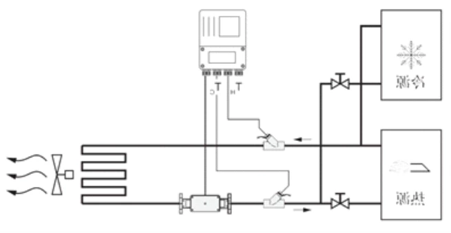
Noted: the product strictly prohibited to be used in explosion-proof occasions.
